Many years ago I enjoyed taking part in radio direction finding competitions on 2m run once year by local clubs. These rarely run now and even if they did I would not take part as they involved travelling around by motor car which is wasteful and I don’t like driving. I was aware from RadCom that radio orienteering competition took place nationally and internationally but these look like they are for serious athletes and besides I didn’t want to drive or even fly to take part. Fortunately thanks to Roy G4JAC attending Suffolk RED I discovered that Goldilocks style there was an RDF activity just right for me.
I now also had reason to build my own receiver. I wanted it to be as simple as possible but perform well enough to use in competition. I found few designs for 160m DF Receivers and several more for 80m.
80m DC Receivers:
G3ZOI ROX-80 Simple design with varicap diode and polycon capacitor tuning options.
WB6BYU Dale Hunt’s beautifully simple design using commonly available cheap components.
These DC receivers did not have enough gain for the low power transmitters used in the multiDX competition and I suspected they would not have sufficient selectivity especially if I just added more gain so I looked at superhet designs below:
VK3YNG Single conversion superhet using BF904 dual gate MOSFETs and SA612 as a mixer and product detector.
LZ1PPL Similar approach to VK3YNG but using an SI5351a for VFO.
DF1FO Nick Roethe’s Rolls Royce design made commercially by Rig Expert and seems very popular in European competitions I’ve seen in youtube videos.
The US based site Homing In has many links and info.
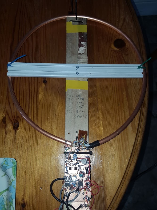
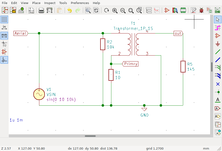
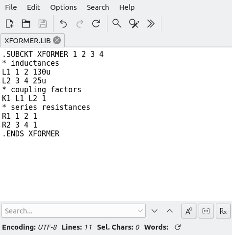
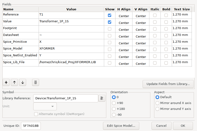
My prototypes