Many years ago I enjoyed taking part in radio direction finding competitions on 2m run once year by local clubs. These rarely run now and even if they did I would not take part as they involved travelling around by motor car which is wasteful and I don’t like driving. I was aware from RadCom that radio orienteering competition took place nationally and internationally but these look like they are for serious athletes and besides I didn’t want to drive or even fly to take part. Fortunately thanks to Roy G4JAC attending Suffolk RED I discovered that Goldilocks style there was an RDF activity just right for me.
I now also had reason to build my own receiver. I wanted it to be as simple as possible but perform well enough to use in competition. I found few designs for 160m DF Receivers and several more for 80m.
80m DC Receivers:
G3ZOI ROX-80 Simple design with varicap diode and polycon capacitor tuning options.
WB6BYU Dale Hunt’s beautifully simple design using commonly available cheap components.
These DC receivers did not have enough gain for the low power transmitters used in the multiDX competition and I suspected they would not have sufficient selectivity especially if I just added more gain so I looked at superhet designs below:
VK3YNG Single conversion superhet using BF904 dual gate MOSFETs and SA612 as a mixer and product detector.
LZ1PPL Similar approach to VK3YNG but using an SI5351a for VFO.
DF1FO Nick Roethe’s Rolls Royce design made commercially by Rig Expert and seems very popular in European competitions I’ve seen in youtube videos.
The US based site Homing In has many links and info.
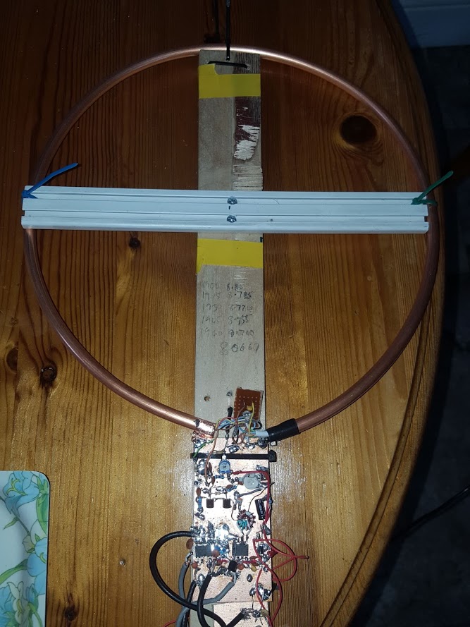
My prototypes
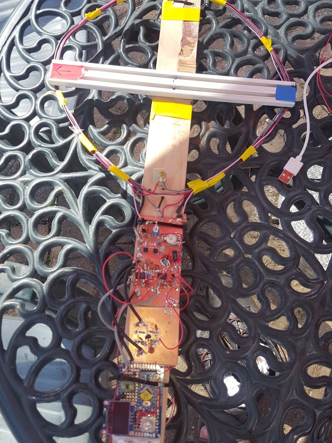
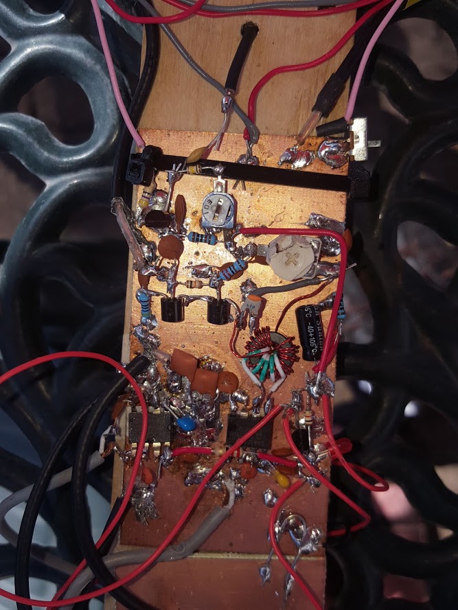
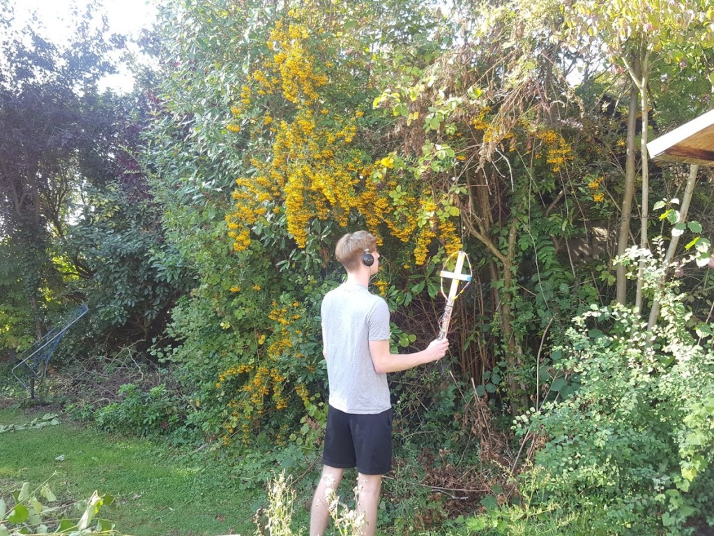
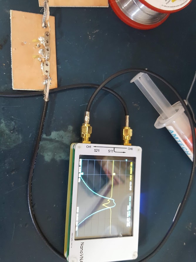
Hi Chris
great site you have here. I’d like to build the vk3yng but I forgot the manufacturer of PCBs you told me about. I’d also like to build a transmitter and Fibber. Could you point me in the right direction?
It was nice to meet you last Sunday.
73s Russell 2E1RUS
LikeLike
Russell, The PCB house I used was https://jlcpcb.com/ there are others such as pcbway. Keep in mind the vk3yng design is for 80m and the local df hunts here are on 160m but it’s not that big a deal to modify the design. If you are going t use that design as is make sure you can source the components – you might have trouble finding those coils. The vk3yng project includes a simple transmitter which he recommends building first. Building a dibber is a whole other game and only makes sense if you a building a full set with matching triffids. and a whole software package to go with it. Chris
LikeLike
Thanks Chris. That’s put a spanner in the works. Is it possible you to point me the direction of making my own Receiver, Transmitter and Dibber.
I saw the diagram with pin layout and completely forgot it was top band.
I’m looking forward to the next one next month.
Best
Russell
LikeLike
Russel,
Take a look at this kit. The manual has instructions for modifying for 1.8 MHz. I’d forgotten I’d built one years ago. I just dug it out. I replaced C3 with 220pF and soldered 47 pF across the back of trimmer cap T3 and it covers 1.90 MHz to 1.96 MHz. For a test transmitter you could use any simple one transistor oscillator circuit but finding crystals on 1.9 MHz is hard so I suggest something based on an Si5351a . There is no point in building your own dibber.
Chris
LikeLike